


BOSCH L-JETRONIC FUEL INJECTION IDLE ADJUSTMENT, DIAGNOSTIC AND TUNE UP PAGE for USA models of Alfa Romeo Spiders 1982-1989
I need to give a BIG thanks! to Eric Russell for providing us with this page. Special thanks to 'PapaJam' and 'Tifosi' from www.alfabb.com for proof-reading and other input.
Update 7-29-2007. Eric Russel provided some improvements to sections 3 and 4. Thanks Eric!
Update 9-30-2015 Missing pictures fixed and other minor improvements. This page was originally made with Microsoft Front Page 98 which is no longer maintainable. Hence we have updated it and moved it to our newer site www.hpsimotorsports.com
A lot has happened over the last couple years at our company. My father passed away, and he and I did a lot of Alfa stuff together, so I just didn't feel like updating this page, or doing a lot of work on my vintage (1980's) Alfas. I am happy to say I am back. This page is fixed, all our other tech articles are moving to the new site, and my supercharged Spider is driving!
My children are running the business now and have ECU tunes for the newest Alfas, including the 4C, Giulia, Stelvio, Giulietta Sportiva, and MiTo Cloverleaf cars with the 1.4 Multiair Turbo engine. They also have them for all the other cars using that engine, including the 500 Abarth, 124 Spider, 500L, and Dart. So now the third generation in my family is getting involved in fuel injection, engine management and Italian cars, which makes me very happy.
This article is my old GTV6 L-Jetronic article altered by Eric Russel for the Alfa Romeo Spider. It's also substantially improved with some great pictures and diagrams. The basic information is essentially the same as the older GTV6 article but if you have a Spider it will be easier to follow along here. NOTE there are some significant variations between the GTV6 and Spider systems so try to use the correct article.
![]()
Greg Gordon at Hi Performance Store gave me permission to use the great information he published about the L-Jetronic System in the Alfa Romeo GTV6 and edit it to apply specifically to the 1982-1989 Alfa Romeo Spider.
My comments are in italics. Otherwise, this is all Greg's work - edited to apply to our Spiders.
Below is the engine bay in my 84' Spider Veloce with some of the components to be discussed noted.
AFM = Air Flow Meter
AAV = Auxiliary Air Valve
TPS = Throttle Position switch
CSI = Cold Start Injector
Read on for details about the Bosch L-Jet system.
![]()
Introduction
Please read this before starting any work on your injection system:
With the L-Jetronic system our cars use, about 90% of the complexity deals with about 5% of the running. In other words most of the system's components deal with things like cold starting, warm up, idle, full throttle etc. That means that by the time you have checked and adjusted everything that affects idle you have really checked and adjusted most of the injection system. Just add new plugs, a cap and rotor and you have done a complete tune up. So this article has really turned into a complete fuel injection and tune up article.
You can use this article in a few ways. First you could follow it through step by step. This would very thoroughly check out your injection system. I recommend this method if you have plenty of time, or if your car has more than one problem or if you just purchased the car and want to get it running just right. If your car has one simple problem you can use this article as a sort of trouble shooting and testing guide for specific components. To make trouble shooting easier I have included the symptom's associated with a defect for each part of the injection system.
The sections showing common problems can be found quickly by looking for the *symbol.
If your car is in fine tune but you are looking for ways to gain a little power look for the @symbol.
This article is written with economic realities in mind. I am not going to tell you to go out and buy Bosch testing equipment or to buy expensive new parts you may not need. We will be testing everything with an inexpensive ohm meter and a test light. I will also be telling you how to repair most of the parts so you won't need to buy a new $100 hose or sensor. Everything I say or recommend has been done on my own vehicles with great success.
You should also have and read the official Bosch and Alfa Romeo publications relating to anything you are doing on your car. If anything the official publications contradicts anything I have written then go with the official advice.
![]()
*STEP 1 Eliminate Air Leaks.
Air leaks are easily the most common problem on the Bosch FI Spiders. They can cause all kinds of trouble including difficult starting, lack of power, irregular idle, high emissions, and the famous engines starts, then stalls right away syndrome. A big air leak can cause an explosion in the intake system which can blow the plenum right off the motor, or in some cases blow the main air intake hose off. You should also check to make sure your hoses are hooked up correctly. Compare your engine compartment to the pictures and diagrams on this page and make sure your hoses are hooked up correctly.
To eliminate all leaks you need to start by removing the main air intake hose. I know you don't want to but it's for the best. Now use dish soap, warm water and a brush and clean it very carefully and thoroughly inside and out, it will probably have a surprising amount of oil inside. The accordion section tends to trap a lot of oil and debris so pay special attention there. Now inspect the hose very carefully for cracks, they tend to be common on the bottom of the accordion section and the sections where the other hoses join into it. If you find any cracks you need to determine if they go all the way through. To do this shine a flashlight inside the hose and flex the rubber in the area of the cracks and see if any light passes through. If it does then you have an air leak and it needs to be fixed. Now this hose is about $100! That's a lot of money for a hose. I bought a brand new one and it cracked all the way through again in a just a couple of years. I guess it was one of those "new" hoses that sat on the shelf for ten years until someone bought it. Most auto parts vendors equate "new" with not yet sold. However rubber parts deteriorate with age so you have to be careful. Anyway, I don't buy "new" ones any more and unless yours is really bad I don't think you should either. There is an easy and inexpensive way to repair these hoses. Go to a sporting goods store and get a product called "Shoe Goo" or "Shoo Goo2" which is the same stuff. This is an incredibly strong and thick glue like substance used for repairing the soles of athletic shoes. Fill the accordion section with Shoe Goo and spread it on any other areas with cracks. It dries clear and can be put on smoothly so it will look pretty good. Now put the hose back on the car so the Shoe Goo dries with the hose in its normal position. Spread a little more on the bottom of the accordion section and wait for it to dry. That will probably be the last time you have a problem with that hose, the Shoe Goo lasts a really really long time.
Here my red pointer is touching the accordion section of the main air intake hose which has been treated with Shoe Goo. You can also see the airflow meter (AFM) which the hose connects too at the bottom.
Shown is an Alfa GTV6 but the Spider looks very similar.

Now we need to check the other hoses. Keep in mind that your hoses may be 20 years old and are probably need of replacement. Every time they are handled there is a chance for a crack to develop into an air leak. The best thing to do is replace all the hoses there with a silicone air hose kit (see below) If you want to check and re-use your old hoses that's ok too, just read on. The factory used very high quality hoses that are rubber with a cloth like covering on the outside. The problem with them is they can look fine and still leak! This is because you can only see the outer cloth like covering and not the airtight rubber part which could be full of holes. I am afraid you will have to remove them to really properly check them. There are other ways to check the hoses, like spray soapy water on them with the engine running and look for bubbles or other signs of leakage but this does not work very well. Take the hoses off, one at a time, plug one end with your finger and force air into the other, preferably with an air compressor but orally if there is no other option. Listen and feel for leaks. If it does not leak, the ends are not split and the hose clamps are OK, just put it back on and check the next hose. Check them all and do not forget the small hose that attaches to the fuel pressure regulator. These are frequently cracked where they attach to the regulator and a leak here will prevent you car from ever running properly. If more than one hose is bad or if all of your hoses are the original ones then I recommend replacing them all. The best thing to do is to replace them all with a silicone hose kit. We have silicone hose kits for all L-Jetronic Italian cars available at HPSI Motorsports.
Click here to purchase the 1982-1994 Alfa Romeo Spider silicone vacuum hose kit
Another possible source of air leaks are the four plenum to intake runner connection hoses. These short hoses don't really crack too often, however they do warp and deform. Also their clamps tend to loosen up over time. The best thing to do is replace them all. If you don't want too, just loosen the clamps enough to move them up and down, inspect them, and push down on the plenum to make sure it's fully seated. If it all looks OK then it probably is, just retighten the clamps and everything there should be fine.
Ok, just a little more on air leaks. You may have some air hoses running into the upper right rear corner of the engine compartment and disappearing down a hole. All of these hoses connect to an emissions canister located in a secret compartment behind the right front wheel. To open the secret compartment you will need to un-do some Philips head screws holding its cover in place. Of course just to find the screws you will need to clean away some dirt and road grime from the area. Once the plate is off, the hoses are available for inspection or replacement. It's important to note that this location collects a lot of dirt and moisture and is the first place to start rotting away so it's important to clean it out once a year or so. The canister in there must be inspected for leaks since it's exposed to corrosion and rust. If it's damaged just clean it really well and patch it with J.B. weld, not the quick drying kind.
Behind the right front wheel well is the 'secret compartment' mentioned above. It contains the vapor recovery cannister. Brush off the dirt from the splash panel to find some Philips head screws. A couple of hoses pass through a grommet in the top of the splash panel.
I placed my camera on the front tire, looking aft.
Here's what the vapor cannister looks like:

The vapor cannister in our Spider looked quite good. I brushed off some loose rust and painted the top with POR 15.
Here's the space behind the splash panel. The cannister is hooked onto the 'hanger' and secured by one nut.

Note there are two hoses on top (they pass through the splash panel and then go into the engine bay) and one hose at the bottom. The bottom hose goes into the cockpit, runs along the right inner sill (under the carpet) and makes its way all the way back towards the trunk to an 'expansion' tank.
Note #2 - there is another hose (plastic tubing, actually) that runs along the right inner sill for the manifold pressure sensor. That sensor is located under a trim panel behind the right door. More about this item later.
Here's a schematic of the vapor recovery system.
One other system to check. The oil vapor recovery system has a number of hoses, some of these connect to the intake plenum. Leaks from those hoses -or- a hose plugged with crud will adversely affect running. I suggest you make sure the oil separator and its hoses are intact and clear. The separator can be removed and flushed with solvent (carb cleaner works well). Most likely to plug up is the small diameter hose that exits the bottom of the separator and leads to the base of the dip stick tube.
The worst place to have an air leak is at an injector seal. Fortunately it's also the rarest place for an air leak. Each of the car's four fuel injectors press into a small rubber seal in the intake runner. These seals are often forgotten since they are out of sight below the injectors. However when they get old they can leak. Most people think that a failed lower injector seal will result in an external fuel leak but that's not the case. A failure of a lower injector seal will cause an air leak into the engine not a fuel leak out. There are a few reasons this is the worst air leak to have. Most air leaks are upstream of the intake plenum which means that these air leaks are divided evenly among the cylinders. In those cases the O2 sensor will try to richen the mixture to compensate and during steady driving will do a fairly good job. Your car won't run just right and it will not have full power but at least during normal driving your mixture will be close enough so your engine won't suffer any damage. All of the air leaking in through a bad injector seal will go into just one cylinder. The O2 sensor will try to compensate by richening the mixture in all cylinders which is all it can do. The result will be a mixture that is too rich in three cylinders and too lean in just one. Running the car like this for an extended period of time can result in burned valves, damage to the valve seat area and excessive cylinder and piston ring wear. In short this is the worst air leak to have because not only does it cause the running problems the other air leaks do but over time it can result in ENGINE DAMAGE!
@ I should mention that with the intake hoses off, it's an excellent time to adjust the valves. Valve adjustment is beyond the scope of this article but with the hoses out of the way it's a good time to do it.
![]()
*STEP 2 Electrical Grounds
Next to air leaks bad grounds are easily the second most common problems on L-Jetronic cars. There are not too many of them to deal with, but they are all critical. Bad grounds can cause a huge variety of problems. There are so many in fact that the official Bosch trouble shooting guide lists bad grounds as a possible cause for 80% of the problems they recognize. These problems include drivability problems during warm up, starting problems, the starts and stalls syndrome, irregular idle, lack of power, high emissions and high fuel consumption. The good news is that grounds are easy to find and fix so this won't cost you any money.
When I start working on grounds I start right at the heart of the injection system, the injection ECU.
***DANGER WILL ROBINSON DANGER DANGER***
It is quite possible to ruin the ECU or other electrical components of the L-Jetronic system so please read carefully and do not skip ahead on any of this electrical stuff.
We will be disconnecting the ECU soon. It is very important that the ignition switch be OFF whenever disconnecting or connecting the ECU. As an added precaution you may want to disconnect the car's battery before proceeding, this will insure the ignition is off. A bad ECU ground can cause every type of running problem the car can have. However the one thing it can't do is stop the car from running at all. Even if the ground is totally removed the car will start fine but will cough if you advance the throttle more than about a millimeter. It's actually possible to drive the car without an ECU ground but your top speed will be about 45 mph and it will take about five minutes to get there, and yes I have tried this!
The Bosch L-Jetronic system as used in the '82-89 Spiders has two ECU's (aka computers).
The fuel injection ECU is under the horizontal 'parcel shelf' behind the seats. A couple of velcro strips secure the front edge of this carpeted panel and a couple of hard to find screws hold the rear edge. (I don't bother with the two rear screws.) Near the FI ECU is an in-line fuse for the fuel pump, two relays, and an 'altitude compensation device'.
The ignition ECU is under the vertical panel ("side lining") behind the passenger (right) side door. Next to the ignition ECU is the manifold pressure (i.e. vacuum) sensor. A long plastic tube runs from the intake plenum, through the firewall, along the inner sill (under the carpeting) and back to the sensor. If your Spider is making a rather monotonous whistling sound, the pressure sensor has likely sprung a leak.

Make sure the ignition is off. Some people say it's also possible to damage the ECU with static electricity from your body. This is the same static that shocks you when you walk on new carpet and touch something metal. I don't know if it can really damage the ECU but I don't take any chances and you shouldn't either. To eliminate this risk, I don't take the ECU out of the car, I work on it right there in the passenger seat, and if I get out I make sure I am not touching the ECU, car, and ground at the same time. Now disconnect the wiring harness from the ECU. There is a little tab to move and then one end of the harness will pull free and it will pivot on an attachment point at the other end. Just unhook it there and it's disconnected. Now just unbolt the ECU from the car so you can hold and inspect it. Look at all the terminals and inspect them for corrosion. The grounding terminal is on an end and is usually the only one to corrode. Clean all the terminals with a toothbrush and electrical contact cleaner. Spray cleaner into the harness too and put it all back together.
The Spider has a few ground connections you should check, clean and tighten. Once the terminal and connection area is clean, I like to apply some di-electric grease to stave off further corrosion. The main battery to body ground is in the trunk. Follow the negative battery cable to where it bolts to the floor of the trunk. Clean and secure that one. While you're at it, clean and tighten the battery connections, also. On the intake side of the engine are a couple of grounds. One on the intake itself and one on the cam cover, under one of the bolts securing the AAV (Auxiliary Air Valve). Clean and tighten all of those. (note - on my Spider I attached both of these grounds to the bolt on the intake. That way there is one less item to fiddle with when I R/R the cam cover.)
Finally, there is (or is supposed to be...) a ground strap between the bellhousing and a metal tab in the transmission tunnel. I say "supposed to be" because sometimes this strap goes missing during a gearbox R/R. If your car doesn't have it, get one. They are sold at any auto supply store.
Here is the bell housing to body ground strap.
(I took this photo from underneath my Spider, looking up.)
And here are the main ECU (computer) grounds on the intake. 
Get some wrenches, a solution of soapy water (I use dish soap because it cuts grease and oil like crazy, it's cheap and right there in the kitchen, just don't use it to wash the body because it also eats wax). You also need a small brush and some fine Emory cloth. Unbolt the ground, clean up the area with the brush and soapy water, then remove any corrosion or rust with the emory cloth. Put it all back together and you should not have any problem for 10-15 years. If you want to be really professional put some silicone terminal grease over it to protect the ground from corrosion.
***DANGER DANGER*** Do not connect the battery cables to the wrong terminals or you will wreck the ECU. Put the battery back in carefully. Remember that the negative terminal is the one that grounds to the body, it should be black and the other one should be red but on cars this old they may have been changed so be careful.
Just one more point to make while we have our head under the hood. Note that the are supposed to be aluminum washers under the two rear cam cover bolts. Without these, the cam cover is 'ungrounded'.
Air leaks and grounds are easily 90% of all L-Jetronic problems so if you have followed along your car is probably fine now. Next we will be testing all the components and making a few changes and adjustments to improve things.
Ok, the next thing is not really a ground but it's a related and very important electrical item. What's more it can stop your car dead, right now with no warning. I am talking about the fuse-box. ANYTIME something goes wrong with your Spider check all the fuses. If they all look OK rotate them and make sure they are seating well.
It has been my experience that sometimes, even if they look OK, old fuses sometimes just get fussy and quit working (like me...). While you're cleaning up the fuse box, I suggest you replace them with new ones.
Here's a snip from the owner's manual for the 1984 model so you can replace them with the correct size (amperage) fuse. #1 starts on the left.

One other important fuse is located near the fuel injection computer (under the parcel shelf behind the seats). This is an in-line fuse for the main fuel pump. An 8 amp fuse is specified.
On later cars, Alfa changed to blade type fuses. They are possibly more reliable than the "bullet" style (and it's certainly easier to find replacements locally). Here's a list of the fuses for the 1988 model.

Note that fuse #1 is listed as 25 amps. This is per an update from an Alfa service bulletin (originally it was listed as a 20 amp fuse).
You should have spare fuses in your Alfa, especially spare 8 amp fuses since those are the ones that make you car go! It's possible and not too uncommon for fuse #5 and #8 to blow in such a way that they make contact and look fine but are not really carrying enough current. If you have any injection problems you should replace these fuses. Of course the fuses' contact in the fuse box itself could have problems too so it's a good idea at this point to disconnect the battery, remove fuses #5 and #8 and any others that look suspect or are associated with a system that is not working properly and clean out the contacts with electrical cleaner and a small toothbrush. Then put the fuses back in wait for the contact cleaner to dry and reconnect the battery.
![]()
*STEP 2.1 Electrical Voltage Check
While not specifically part of the grounding system, this is a good time to check system voltage. The L-Jetronic system requires a certain minimum voltage to "wake up" and send the signal for spark & fuel. A marginal battery may crank the engine over with seemingly adequate cranking speed but the available voltage can drop below the minimum threshold.
Connect a voltmeter to the battery. Either position the meter so you can see it from the driver's seat or enlist a trusted helper. With all accessories off, a good battery will read 12.3-12.6V. Next crank over the motor (transmission in neutral!) and see what the meter reads while the starter motor is engaged. The second reading should be above 10 volts (preferably above 10.3V). If the voltage readings are low, the battery needs charging or replacement.
![]()
*Step 2.2 Flywheel Sensors
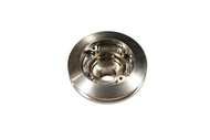
The Bosch ECU (computer) relies on two sensors that tell it the crankshaft's speed (RPM) and position (timing). There is a magnetic button on the flywheel's circumference and the two sensors are located on the bellhousing. It is vital that the flywheel is installed correctly. It is not "dowelled" and can thus be installed in six different positions (5 wrong and 1 right...). If the flywheel has been removed (say during a clutch job) and not re-installed correctly, your car will not run right (if at all). There is a small mark on the edge of the flywheel. With the #1 piston at TDC on compression this mark must be at the top - "12 o'clock".

Here's a picture of a flywheel showing the mark (which I highlighted with some paint) at the "16" and the magnetic button at the "10".

The two flywheel sensors are identical but they must be connected to the wire harness correctly. The harness connectors are color coded grey and black. Here's a diagram from the Alfa Shop Manual.
Note that the sketch makes it look like the connectors are at the bellhousing. They ain't! The two connectors can be found near the wind screen washer fluid reservoir. The black connector goes to the upper sensor and the grey connector goes to the lower sensor. Here I have circled the two harness connectors.

If either (or both) of these sensors are faulty, the ECU will not know the crankshaft's position or that it is moving and thus will not send out the signals for spark & fuel.
To test the sensors you will use an ohm meter. NEVER touch the ohm meter's probes to the harness side of the connector. That will send electrical current to the ECU possibly damaging the ECU.
Disconnect the harness to sensor connector (one at a time will avoid mixing them up). Note that the Bosch connectors have a small wire clip to hold them connected. Do not try to pull them apart with force. Use a small screwdriver to move the retaining clip out of its locking groove, then undo the connection.
Below is a close-up of the sensor's connection to the harness. Remember that we will only be touching the ohm meter to the sensor side of the connection - never to the harness side. A good sensor will measure between 800 and 1250 ohms between the terminals indicated in the photo.. The other terminals should show infinite resistance (no connection).
Here is a spare sensor (everyone keeps a spare, right?) with my ohm meter showing a good reading. You can also see the mounting block that attaches to the bell housing. If (when?) you need to replace a faulty sensor, make sure not to lose the mounting block - the new sensor does not include the mounting block.
![]()
*Step 2.3 ECU controlled Variable Valve Timing
Variable Valve Timing (VVT) allows your car to have a smooth idle & reduced emissions and full power above idle speeds. Alfa introduced the centrifugally activated VVT in 1980. This type VVT continued into the Bosch L-Jetronic Spiders until the '83 or '84 models when it changed to a solenoid activated VVT - controlled by the ECU. Here is a description of the adjustment and testing of the later type VVT.

The electronic version of the Variable Valve Timing device is controlled through an extra wire on the throttle position switch located on terminal 3 of the TPS (Throttle Position Switch) harness plug. It becomes active when the throttle is opened far enough to move the TPS through 55 degrees of motion and is strictly an 'on-off' affair with no intermediate steps or range involved. The VVT moves the intake cam from it's stock setting to 11 degrees of advance for more aggressive performance.
Checking function, engine off:
With the ignition switch on, move the throttle linkage toward full then listen for the 'click' of the VVT solenoid to activate once you are at or near full throttle. You can also look through the sight hole on the VVT mount to see if the solenoid pin extends when nearing full throttle then retracts when you release the throttle.
Checking function, engine on:
Start the engine and allow it to warm up then remove the connector from the TPS and jumper terminal 18 and 3. The VVT should engage and you will immediately notice the idle running rougher, if not outright stalling. Disconnect the jumper and the engine should recover back to a smooth idle if it did not stall. If testing using either of the above methods indicates the VVT does not function, first check the fuse located near the coolant reservoir bottle, the 3 wire harness connector right near that, the harness connector on the VVT solenoid and the connector on the TPS.
Note: if all the connections are good, the fuse is good and the wiring intact, it is possible that the circuit board within the VVT harness connector has been damaged or burned out. Very uncommon, but not totally unheard of. There is little that can be done for it other than finding a good used spare, or if you're very lucky, someone who can rebuild the existing PCB with all the appropriate electrical components.
Setting the VVT solenoid:
1) Remove the VVT harness connector by loosening the lock screw and slipping the connector straight off toward the radiator. * There are 2 bayonet connectors on the solenoid, so do not twist while removing it.
2) Using a suitable wrench, loosen the lock nut anti-clockwise 1-2 turns.
3) Unscrew the VVT 1-2 turns or until you can see a definite gap between the tip of the VVT and the cam plunger through the sight hole.
4) There is a large opening in the bottom side of the VVT mounting bracket. Reach under into there with your finger and depress the cam plunger to its fullest range, then slowly release it until it stops on it's own. *Do not try to pull it further out. It can come further out, but if you do it will cause the rest of the setup to not function properly. You only want it to come out as far as the internal spring load pushes it.
5) Very slowly and while looking through the sight hole, begin to screw in the VVT solenoid until the tip of the tapered portion appears to just touch the tip of the cam plunger (*it won't be, but it will look like it). Do not screw the solenoid in so far that the cam plunger begins to depress or even move for that matter. If you do, you'll have to start again. * The actual activation rod of the solenoid is slightly recessed within the angled tip of the solenoid body. There is no need to try and get the cam plunger tip to touch the tip of the activation rod, merely even with the tip of the angled portion of the body. The factory service tool functions the same way when it is available and employed. The idea is to get the cam plunger to move far enough to cause the oil flow to change within the VVT mechanism on the camshaft. If it's pressed in too far it will bottom out and cause wear on the plunger, VVT solenoid, and most notably, the rubber liner on the threaded sleeve of the VVT solenoid mounting bracket which is totally irreplaceable.
6) While holding the solenoid in position, gently snug up the lock nut to finger tight, then with a suitable wrench to around 10 ft lbs torque. Over tightening can potentially damage the rubber liner in the mounting bracket and is unnecessary since the solenoid only functions in an in/out fashion with no rotational stress what so ever.
7) Reconnect the harness to the VVT and conduct either test as described above. If it functions, tighten up the locking screw on the VVT connector and straighten up the wiring that may have been moved.
If all has gone well, you now have a properly set VVT and will get the benefit of reduced emissions along with slightly better fuel economy while driving in a civil fashion and the advantage of a hotter cam angle when you decide you're not.
![]()
Step 3 The cold start and warm up system.
Now we will test all of the components involved in cold starting and warm up. These two phases of operation are the reasons for a lot of the L-Jetronic's complexity. The components involved in these phases are the cold start injector or CSI, the injection's coolant temp sensor or CTS, the thermo time switch or TTS, and the aux. air valve or AAV.
Before we go any further I think it's quite important to back up and review some basic concepts common to automotive engines. Cold engines require three things to start that they do not require at other times. They are a squirt of fuel directly into the manifold, a richer than normal mixture for staring and warm up, and an idle position for the throttle that is a little farther open than normal. Lets consider how the cold starting procedure works on an older carbureted car with a manual choke. First we step on the gas pedal at least once, then pull out the choke cable, and then turn the key to start it. That first step, stepping on the gas pedal, causes the accelerator pump to squirt fuel into the manifold. The second step, pulling out the choke cable does two things. It richens the mixture by cutting off air which is why it's called a "choke" (a very small number of carbs do not cut off air when choked but bleed extra fuel into the motor instead) and it activates the fast idle function of the idle stop by holding the throttle open a little extra at idle. As soon as the engine starts the choke will open slightly and be opened more and more until the engine is warmed up when it will be all the way open.
The L-Jetronic system does all these exact same things the old carbureted cars did, it just does them automatically and in a different way. First it squirts fuel into the manifold using the CSI instead of an accelerator pump. This happens automatically under certain conditions and you have no control over it. Next the designers needed a way to richen the mixture during cold start and warm up and they did this in a simple and clean way which involves no moving parts. They did this with the CTS. This little sensor mounted on the thermostat housing measures coolant temp and sends the information to the injection ECU. The ECU then adjusts injector duration to richen the mixture during cold running. The thing was to come up with a fast idle position for the warm up period. This problem caused a real headache for the designers of the L-Jetronic system. They knew they needed to have a way to advance the throttle during the warm up period but they could not do that for two reasons. First they were trying to minimize the number of moving parts in the system and a fast idle stop would complicate the linkage. However the biggest reason was they could not move the throttle off its normal idle stop during idle was because then the throttle position sensor, or TPS (which we will cover later in this article) would tell the ECU that the engine was no longer at idle. This would have caused a lot of problems including a loss of fuel economy and an increase in emissions. To solve this problem the designers used a device new to the automotive world, the AAV. The AAV opens up when the engine is cold to allow extra air which is metered by the air flow meter to enter the engine. The air flow meter then signals the ECU for more fuel and thus when the AAV is open the engine gets more air and more fuel and thus idles faster. This does the exact same thing as pushing down on the gas pedal slightly except it does it without taking the TPS off its idle position.
* We will test the Coolant Temperature Sensor (CTS) first. The CTS is a critical item, if it is not connected the car will not run. They rarely fail and about the only thing that does go wrong is corrosion on the probe or a bad electrical connection. CTS problems can cause all types of starting problems, poor fuel economy, and/or high emissions.
***DANGER DANGER DANGER***
Do not ever touch an ohm meter or anything else that sends current to the terminals on the wiring harness. That will send current into the ECU where it is not expecting it and it could damage or destroy the ECU or other components. All testing procedures we will be doing involves touching the ohm meter to the component being tested like the CTS itself, NEVER to the wiring harness. If anyone is unclear about this ask before you proceed, this is critical.

Close up of CTS and TTS.
When your car is fully cooled off, like after sitting overnight, get your ohm meter, open the hood and disconnect the CTS. The CTS is connected to the wiring harness via a standard Bosch connector, it WILL NOT just pull off, you need to get a tiny screw driver and release the metal clips that secure it, then it can come off. Be careful and take your time removing these connectors to avoid breaking them. Once it's free, tuck the connector away somewhere safe so you will not be tempted to touch it with your ohm meter. Once the connector is off and tucked look at the CTS and you will see it only has two terminals. Make sure they are fairly clean and connect one to each of the probes on the ohm meter and read the resistance. between the two terminals. If the temp. is 14F/-10C you should read 7-12K ohms. If the temp is 68F/20C you should read 2-3k ohms, and the car is fully warmed up to 176F/80C you should only read 250-400 ohms. I like to check the car when it's cold, then after it warms up I check it again. If the values look good put your ohm meter away, spray all the terminals on the CTS and its wiring harness plug with contact cleaner and hook it back up.

Ohm meter connected to the CTS terminals. Cold engine ~0C/32F
Test the TTS in a similar manner.
NEVER touch ohm meter's leads to the harness connector!
* Next we will check the Thermo Time Switch. A bad thermo time switch can only cause two problems, either difficult or impossible cold starting or difficult or impossible hot starting, depending on how it fails. The TTS is also mounted on the thermostat housing. The TTS will send power to the CSI if the engine temp is below its specified setting. The TTS also has a bi-metal strip that heats up to limit how long it will signal the CSI to squirt. This prevents the CSI from functioning longer than a few seconds (to prevent 'flooding').
With credit to Alfa BB members
Animate, Tifosi, & Elio Comello, here is some
additional/corrected info about the Thermo Time Switch of the Cold Start
System.
      To test the TTS we remove it's connector
just like we did with the CTS. Again you will see it has two terminals. Connect
your ohm meter to them and check for readings as outlined below. If it checks
out OK, clean the plug and terminals with contact cleaner and hook it back
up.
below 30C/86F = 25-40 ohms
above 40C/104F = 50-80 ohms
2. Between W and ground:
below 30C/86F = 0 ohms
above 40C/104F =
100-160 ohms
3. Between G and W:
below 30C/86F = 25-40 ohms
above 40C/104F =
50-80 ohms
Photo of TTS's terminals:

If these components tested fine odds are you should just move on, however it's possible for these components to test fine but be nearing their death due to corrosion. To really make sure they are OK, it's best to pull them out and clean off their probes with a rotating wire brush. Of course when you remove them coolant will come pouring out of the thermostat housing so it's best to do this when you have to change the coolant anyway.
Next we need to check the Cold Start Injector (CSI) and in doing so will also be double checking the function of the TTS. The cold start injector is a 5th fuel injector that injects fuel into the intake plenum under the following conditions. First the starter motor has to be cranking the motor and two the TTS has to be closed which means if it's working properly the coolant temp has to be below 86F/30C. The cold start injector is located on the intake plenum at the rear. It has a hose going to it and a Bosch electrical connector similar to the ones for the CTS and TTS except it's usually blue. Testing it will be simple - you just need an Allen wrench to unbolt it, a small can, and a competent helper to activate the starter motor.
* A bad CSI can cause starting problems, high emissions, poor fuel economy and poor idling qualities.
When the car is cool, and that means a coolant temp of below 80F, and colder is better, unbolt the CSI. Be careful not to drop the little Allen bolts and washers that hold it in, they can be hard to find if they fall. Next hold the CSI away from the motor and pointing into the small can. Plug the hole in the Plenum where the CSI normally goes with something that can't get sucked it. If your car has air leaks using your finger could be dangerous so hold a piece of rubber or something against the hole. Anything is OK as long as the hole is fairly airtight and nothing can get sucked into it. Now have a friend crank the motor over for a few seconds. The car may start, but that's OK (obviously take precautions here, car in neutral, clutch in etc.).
Watch the CSI, it should spray a nice stream of fuel into the can and stop the second your friend stops cranking the starter. If it does both the CSI and TTS are working properly for cold starting. Perform this same test again with the car warmed up and make sure the CSI does not spray any fuel. If it does not then your CSI and TTS are working properly for warm starting. Now as an advanced check (this is not really necessary) you can disconnect your ignition and perform the same test. This time the engine will not start but watch the CSI, it should start spraying but stop on its own in a few seconds even with the engine cranking. This is a design feature intended to prevent flooding.. It should not fire for any more then 8 second before stopping.
* The last and most troublesome part of the cold starting system is the Aux Air Valve. I hate the Bosch Aux Air Valve. A faulty AAV can cause the following problems. Difficult or impossible cold starting, the starts and stalls right away syndrome, poor running during warm up, irregular idle, and last and worst horsepower loss.
Here on my tool bench is a GTV6's AAV (the Spider's looks the same). My screwdriver is touching the adjustment nut.
The AAV is located on the right side of the cam cover. It has a standard Bosch electrical connector and a hose connecting to it at each end. It is simple in theory. It has a bimetallic strip inside that expands and contracts when it gets hot or cold. When cold it contracts and opens up a passage inside the AAV which allows more air to pass through it and into the intake plenum. This causes the AFM to increase injector duration and it increases the idle speed. As the car warms up the AAV's passage closes slowing down the idle. I should note that the idle speed should never really changes much during warm up. The engine will idle at a higher speed as it warms up with a given amount of airflow so what the AAV is actually doing is providing extra air when cold and then cutting off the extra airflow as it warms up to keep the idle about the same. The electrical connection has nothing to do with any other system. It is simply provides electrical current to the AAV to cause it to warm up and close a little faster than it otherwise would.
The AAV's most common problem is it gets jammed either open or closed. This happens because the expansion and contraction of the bimetallic strip is not too powerful and it can be easily overcome by oil and crap that gets into the intake system.
There are a few ways to check the AAV but only one way is reliable. I am afraid you are going to have to pull the thing off the car. With it off the car clean it out with carb cleaner or something similar, and then clean out all the carb cleaner with dish soap and water. This cleaning process is needed about once a year in order to keep an AAV operating in top form. When it's really clean put it in the freezer and when it gets cold look through it and you should see a large opening inside. Now heat it up to about 150F and it should be fully or very nearly fully closed. If it does not open up fully you will have cold starting and running problems. If it does not close fully you will have an irregular idle and power loss.
Cleaning the AAV almost always seems to fix them. If it doesn't you may try playing with the little adjustment nut on it. It seems that some AAVs close fully, but don't open very far. This is optimum for horsepower but not for starting in near freezing temperatures. Others open a lot giving great cold starting but don't close all the way which robs some horsepower. With the adjustment nut and a lot of patience you can set up your AAV to suit your needs...well, sometimes...maybe. Furthermore if you adjust the AAV you will probably need to re adjust your idle speed. To optimize it for cold starting take a cool AAV that is at least partially open and jam something inside it to keep it from closing. Now loosen the adjustment nut and then force the AAV to open up a little more. Now while holding it open tighten the nut. That will bias the AAV toward effective cold starting.
@ To bias it toward more horsepower you can just loosen the nut on a warm AAV, it should then close fully. At this point tighten the nut. You will gain a little power but cold starting will suffer. If you fiddle with it enough you can get it to open most of the way and close most of the way which is how most of them work from the factory. If you have cleaned it, adjusted it and still can't get it to open and close properly you will have to buy another. They cost about $70 for a GTV6 and as much as $130 for some other cars.
@ If you want you can buy a manual valve. It's a permanent fix and will never need to be replaced or cleaned. It also provides even better cold starting and slightly more power than a perfectly functioning Bosch AAV. It's operated by a manual cable, pull it out for starting and push it in after a few minutes of running. The manual AAVs are for sale from Greg Gordon at HPSI Motorsports.

Thank you to Larry Simpkins for sharing this image of his Alfa Spider! He has the HPSI Silicone Vacuum Hose Kit, the Air Oil Separator Hose Kit, the HPSI Silicone Radiator Hose Kit, and of course the Manual Aux Air Valve installed.
![]()
Step 4 Fuel Pump and Fuel Pressure Regulator. * Fuel Pressure in the L-Jetronic system is quite critical. A fuel pressure problem can cause about every possible problem you can think of. Fortunately there are only two components involved and they are both easy to check and reliable. However if they are bad you will need to replace them. I don't have any Shoo Goo tricks for this part of the system. I do suggest replacing the fuel filter before performing the tests on the fuel pumps and pressure regulator if you are unsure of its age. It's recommended that you change the fuel filter every time you change spark plugs.
The fuel pumps are controlled by the drive relay (next to the FI ECU). The drive relay gets a signal from the coil via a shielded (covered with a braided covering) white wire. The drive relay is unique in that it expects a pulsing signal from the coil (as the coil field cycles with spark plug firing). When the ignition switch is first turned to 'on' that energy spurt to the drive relay briefly powers on the fuel pumps. When the key is next turned to 'start' and the engine is cranked a valid signal from the coil to the drive relay again powers up the fuel pumps. And a running engine will keep the pumps powered on. This functions as a safety device. If the engine stops running (as in an accident) the fuel pumps will cease running.
The L-Jetronic Spider has two fuel pumps. One is an 'in-tank' pump located, umm, in the tank. The other pump is the main fuel pump. The main pump is located underneath the car, just forward of the rear axle on the right side. If your CSI (Cold Start Injector) passed the functional test described above in Step 3, it is quite likely your pumps are working fine and the fuel pressure is good. If you want to test it further, read Greg's 'shade tree mechanics' procedure below. (Proceed at your own risk - remember you are dealing with fuel under fairly high pressure.)
One other item to check. The earlier model Spiders ('82 to '83 or '84) came with an inertia shut off switch to remove power to the fuel pumps. It is black box, about the size of a pack of cigarettes, located on the firewall between the wind screen washer reservoir and hood latch. It has a button on top to reset it if it should be tripped by a large enough jolt (such as an accident). This item was deleted on the later cars. In these cars the drive relay is expected to remove power to the fuel pumps.
If the pump does not run check the fuel pump main fuse (near the FI ECU)., if the fuse is good check electrical current at the pump with a test light or volt meter. If it does not have current the problem is probably the relay set (located next to the FI ECU). If it does have current and does not run you need a new or rebuilt fuel pump. The rebuilt ones are just as good. If it is running, move on to the fuel pressure test.
Important! Never run the in-tank pump dry or test it by applying 12 volts while it is out of the tank. It MUST be immersed in fuel for cooling and lubrication. Even a few moments dry running could ruin it.
Now we will check fuel pressure. This injection system requires 35.6 psi. It seems that most fuel pressure gauges that measure values that high are really expensive. There is however an inexpensive way to check. Remove the cold start injector's fuel line from the injector (it is attached with a hose clamp). Be careful since fuel there is under pressure and will spray out for a second or so when you remove the line. We will be using a cylinder compression tester to check the pressure. It can measure fuel pressure in this range just fine and it's made to have oil, fuel and other contaminants forced into it under pressure so this probably will not damage it. While you hold the compression tester into the CSI's fuel line, have a friend turn the ignition switch to 'start', which will make the fuel pump run. Now of course if you are not holding it really tight you will get fuel everywhere so be careful and have rags ready to soak up any spilled fuel. (I suggest EYE protection if you want to test the fuel pressure in this manner.) If it does not read about 35 PSI your fuel pressure regulator is bad. Now I just know there are some of you out there who don't have a compression gauge. Well there is another way to check pressure, well sort of. This is not as terribly accurate but it's better than nothing. Put the CSI's fuel line into a empty and clean one gallon container and run the pump using the previously described method. A properly functioning pump and regulator will fill the gallon jug in just about two minutes.
![]()
Step 5 Throttle Position Switch
The TPS is located on the intake plenum.
First the adjustment. When the throttle comes on or off idle you should hear a faint click. There should be no other noise coming from the switch during throttle travel, it only clicks when coming on or off idle. If it does not click you can adjust the switch by loosening its mounting bolts and turning it. Adjust it so that as the throttle closes you hear the click just before the throttle plate reaches its idle stop. If you can't get it to click you probably need a new switch although it's possible it's just too faint to hear it so proceed with the next checks before buying a new one.
You will need your ohm meter for this procedure. Remove the Bosch electrical connector from the throttle switch being careful not to damage it. If you don't know how to remove Bosch connectors go up to Step 2.5 and read the procedure. Move the harness connector out of the way and DO NOT TOUCH IT with the ohm meter. Now look at the switch's electrical terminals. There are three of them arranged vertically. The top one is terminal #3, the middle is #18 and the bottom is #2. Hey I didn't number these things, if I did they would have been 1,2,3 from top to bottom. Now with the throttle closed you need to check the resistance between terminals 2 and 18. The resistance should be zero. Now with the throttle still closed check the resistance between terminals 3 and 18 and resistance should be infinite. Next we have to do the same checks at full throttle. Have a friend hold the throttle fully open. Check resistance between terminals 2 and 18 and you should read infinite resistance, the opposite of what you had at idle. Check resistance between 3 and 18 and it should be zero. If you do not get these values try adjusting the position of the switch, sometimes just a little adjustment will fix everything. If you can't get the correct resistance values by adjusting it you probably need a new switch. Unfortunately you may need to adjust this switch again if you adjust the throttle's idle stop which you may have to do later in order to get the idle just right.
![]()


![]()
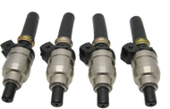
Step 6 Injectors
Like all cars with L-Jetronic our Alfas have one injector per cylinder. These four injectors all open and close at the same time when commanded to do so by the ECU. It's important to understand that the injectors do not really spray fuel, they are just valves that open and close. They have needle valves inside that plug a small hole when closed. They are opened by a tiny electromagnet in each injector that pulls the needle away from its hole enabling fuel to pass into the intake system. When they are open fuel sprays in as a result of fuel pressure, so it's really the pump and fuel pressure regulator that control how much fuel sprays in for a given amount of time when injectors are open. The ECU regulates how much fuel is sprayed in by controlling the amount of time the injectors are open. Your ECU assumes your car has the correct amount of fuel pressure. If you have more or less it will effect your ECU's calculations. The injectors are located in the intake runner at the cylinder head/intake junction. They each have a short black fuel line connecting them to the fuel rail and a grey colored Bosch electrical connector plugged into them. It's not possible to fully test your injectors with them on the car, although the tests that are possible are described here.
* An injector can go bad in a number of ways. They can have external leaks, internal leaks, fail to open, fail to close or they can be clogged with combustion debris. Symptoms of a bad injector or injectors can include difficult or impossible cold or warm starting, irregular idle, lack of power, poor fuel economy, missing, high emissions and external fuel leakage.
Most external leakage is caused by a failed "O" ring inside the injector. This ring seals the plastic part of the injector to the metal part and it is not replaceable. I have heard of people sealing these leaks by coating the outside of the injector with epoxy but I would just buy a new injector. It's a shame Bosch designed the injector so you can't get to this seal without destroying the injector.
It's important to check the injectors internal electrical coil. This is simple, just get out your trusty OHM meter, remove the injector's electrical connector and check the resistance between the injector's terminals. It should be 2-3 OHMs. If it's not you will have to buy a new injector because there is no way to replace the coil.
If your injector is leaking internally or failing to close fully the car might run OK depending on just how bad the problem is. The way to check for this problem is simple. When you change spark plugs inspect them. If one or two are a lot blacker than the others you probably have a leaking injector on those cylinders.. If the leak is bad or the injector never closes, the car will run poorly at low RPM but improve at high RPM when the engine is sucking in enough air to burn the fuel.
It's tough to tell if an injector is stuck closed by looking at the plugs so let's use another method. We can partially check the injectors by performing a "balance check". This will not tell us if all the injectors are equally poor, but it will tell us if one injector has a serious problem. With the engine running remove the injector plugs one at a time and note the rpm drop. If all of the cylinders drop equally then the injectors are all about the same (assuming the engine's cylinders are all in the same condition). This is not a precise test, and will usually only find gross problems.
The most common injector problem and the most difficult to detect is the partially clogged or dirty injector. Unfortunately there is no practical way to check for this problem without pulling out the injectors so we need to use the process of elimination. If you have checked everything else out and your car still has some running problem then it's probably one or more dirty or sticking injectors. Putting injector cleaner in the fuel tank will not clean the injectors. On the contrary it will flush any debris in the fuel system into the injector's filters. Each injector has a filter so small essentially nothing can get past it. The holes in the filter are actually too small to see with the naked eye! Injector cleaner or fuel system cleaner will simply clog up these filters.
Here we see an example of a good injector spraying in fuel.

Here is a picture of a clogged injector. An engine with one or more clogged injectors will never develop full power, and will have high emissions and running problems.

If you find one or more bad injectors there is little choice but to buy new injectors. We have original style and upgraded injectors for Bosch L-Jetronic vehicles in addition to our ultrasonic cleaning and flow-checking service. Let's get one thing clear, THERE IS NO SUCH THING AS A REBUILT L-JETRONIC INJECTOR! Now I know a lot of people claim they are selling rebuilt injectors, and I don't know what they are doing. However I do know that only a few things can be done to them. They can be cleaned, the tiny filter can be replaced, a new pintle cap (tip) installed and the various external seals and spacers can be replaced.
I offer fuel injector flow checking and overhaul service on the latest type of machine for Alfa owners. I have a small fuel injector servicing shop. I have the latest flow checking and injector cleaning equipment. Details are at www.okinjectors.com . The website is not fully developed but you can call us anytime, the operation is up and running. You may also purchase fuel injector service from this website by clicking here.
If you would like your injectors overhauled I can ultrasonically clean them, replace the filters, pintle caps, and all seals for a very good price. I very thoroughly check them all all the RPM levels and pulse widths your injectors will experience on the car. Most shops only check them at idle. I also warranty the injectors I service for 12 months. I have found that when injectors are serviced by other shops they often start to leak about 6 months after the service. This is because the internal seals are delicate and can be easily damaged by the fluids many shops use to clean and flow check. The correct fluids to test and clean these early injectors are $20 a quart so many shops don't bother to use them. I do, that's why I can warranty the injectors I service against external leakage, or any other problems.
After a full overhaul, old Alfa injectors usually work like new and our warranted for 12 months.
Pictured below is a set of injectors before and after overhaul. As you can see before overhaul, the injectors were about 45% apart in fuel flow. It's amazing the car even ran. After overhaul they were all within 3% (well within factory spec). Before overhaul with a target air fuel ratio of 12.5:1 at full throttle the individual cylinders would have been between 12.5:1 and 22.7:1. This would have been disastrous on a high compression or forced induction engine.


When new, Bosch injectors in a given set will normally flow within about 3% of each other. For hardcore applications it's possible to get the injectors within 1% of each other. This normally involves selecting a matched set from a number of injectors. We can provide this service, and we recommend it for high compression or high boost applications.
![]()
Step 7 Air Flow Meter
(note: I have enhanced adjustment instructions for the AFM on step 12)
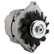
The Air Flow Meter or AFM is one of the most expensive components of the L-Jetronic system. Fortunately they rarely wear out or fail and there are plenty of inexpensive used ones available. The AFM is simple in operation. Air entering from the air filter side pushes a little door open. As the volume of air increases it pushes the door open farther. The AFM measures how far the door opens to determine the volume of air. The AFM also measures the temperature of the air. These two bits of information are combined to determine the total number of air molecules entering the engine and that information is sent to the ECU. The ECU then uses this information to help decide how much fuel the engine needs and adjusts injector duration accordingly. Of course the ECU gets information from many sensors but at full throttle the AFM's signal is primary. That means if you want max power a properly operating AFM is critical.
* A bad AFM can cause the following problems: Difficult or impossible hot or cold starting, the starts and stalls syndrome, lack of power, high emissions, and irregular idle.
I am afraid the official Bosch procedures for checking these things are not too good. They recommend using a Bosch tester which I don't have, or probing with a volt meter. The problem with the volt meter method is the chance of damaging something is greater than the chance of finding a faulty AFM. There is a test involving our trusty ohm meter but it is entirely unreliable. This means we are down to basics here.
First, find the AFM's electrical connector. It's on the left side and is basically just like the Bosch connectors you have dealt with on other components but it's bigger. Remove this connector and spray the connecting points with electrical contact cleaner and then reconnect it. Next, if you did not already do it, read Step 5 paragraphs 2 and 3 and make sure the microswitch enables the fuel pump to run. This also provides a nice opportunity to change air filters. Next you will need to remove the AFM's black plastic cover. The cover is sealed to the body of the AFM with a strong clear glue, probably an epoxy of some kind. Carefully cut away the glue with a sharp hobby knife and then pull the cover off. This is a time consuming process, just work slowly and carefully and don't break the plastic cover. Once the cover is off inspect the internal components for obvious damage and clean out any contaminants. If everything in there looks Ok it probably is. If you want to keep your AFM's stock settings put the cover back on and seal it with RTV silicone, preferably clear or black. If you are looking for a little more performance scroll down to the next paragraph.
Here is a stock GTV6 AFM sitting on my tool bench. (The Spider AFM looks very similar.)
@ It's fairly easy to adjust the AFM to signal the ECU to send in a little more fuel. This mod gives a minor increase in power and better throttle response. It does not effect fuel economy but it can increase emissions. It's a simple reversible procedure. The AFM's door is held shut by spring pressure. We can reduce that spring pressure which will cause the door to open farther for a given amount of air volume. This will cause the AFM to signal the ECU for a little extra fuel. The procedure is simple. With the cover off look at the workings of the AFM and find the large wire shaped like a "W" and secured with a little bolt. That wire secures a gear and keeps the gear from turning. Mark the gear where it is secured by the wire (that's where my screwdriver is touching it in the photo below). Try to make the mark with a sharp knife so it will not wear off. Now hold the gear still and loosen the bolt securing the "W" shaped wire. Once the wire is free of the gear's teeth rotate the gear counter clockwise five or six teeth and secure it in that position by bolting the "W" shaped wire back into place. That's it! put the cover back on, secure it with silicone and you are done with the AFM.
This AFM's spring tension has been loosened five teeth. You can see the original setting on the gear which is marked by silver paint. Paint wears off, so be sure to make a little notch with a hobby knife so you can return it to its original setting if you need to.
![]()
Step 8 Ignition Timing:
Ignition timing is very easy to set on our Bosch L-jet cars. Position the number one piston at TDC on its compression stroke then align the rotor with a mark on the distributor's housing. The ECU (computer) takes over from there. Rotating the distributor will not advance or retard the timing - the computer does that.
Here is a picture of the distributor with the rotor aligned with the mark on the housing. (For this picture I have removed the dust shield normally positioned under the rotor.) The distributor cap is aligned to the housing by a tab the fits into a notch in the housing.
Note that there is really nothing inside the distributor. No 'points', no advance mechanism (vacuum or mechanical). The distributor is really just a four position switch.
Now, how to position the number one piston at TDC...?
The crankshaft pulley will have two marks - F (Fixed - for measuring timing with a strobe light) and P (Point - for TDC). There is (or should be...) a pointer attached to the bottom, left side of the water pump. Put the transmission in 4th speed and push the car slowly forwards until the pointer is aimed at the P. Remember that the distributor turns at 1/2 the rate of the crankshaft so when the mark & pointer aligns number one piston will either be at TDC on compression or at the end of its exhaust stroke. If the rotor isn't aimed at the position for number one cylinder's spark plug (in the distributor cap), push the car to turn the crankshaft one more revolution until the P aligns again.
Here's a picture of the crankshaft pulley showing the pointer attached to the bottom of the water pump and the two timing marks (I cleaned and painted the marks while the engine was apart for a rebuild). You might need a small wire brush to clean the crankshaft pulley to locate the marks. Use a drop of paint on a toothpick to make them easier to see. "White-Out" also works well (but may not last as long).
It is possible that the pointer attached to the bottom of the water pump is either missing or mis-aligned (it is adjustable - which means it can be mis-adjusted...). Here's how I check for TDC in that case. Remove the #1 spark plug (removing all of the spark plugs will make it easier to turn the engine). Then turn the engine (put the transmission in 4th gear and roll it forwards) until you can feel air being pushed out of the #1 spark plug hole. That indicates the piston is on its compression stroke. Next I use a drinking straw (it's stiff enough to be useful but won't ruin anything internally) as an indicator to see when the piston reaches the top of its travel.
As the piston nears the top of its stroke the vertical travel lessens making it hard to determine the exact position of TDC. A better way to determine TDC is to mark the indicating straw when the piston is near TDC - i.e., make a mark on the straw that aligns with the spark plug hole when the piston/straw is about an inch below where you think TDC is located. Also make a temporary mark (chalk is good) on the crankshaft pulley that aligns with the pointer or something fixed on the block. Slowly turn the engine forward past TDC until the mark on the indicator straw again is again aligned with the spark plug opening. Make a second temporary mark on the crankshaft pulley (in line with the same fixed spot on the block). TDC will be halfway between these two temporary marks.
![]()
Step 9 Altitude Compensating Device
This is an interesting little device. It senses changes in altitude by measuring atmospheric pressure. It's not a factor at cruising speeds or at full throttle, it's primarily to help the car idle when driving from low to high attitudes.
On our Spiders, it is located near the Fuel Injection computer under the parcel shelf, behind the passenger seat.
Testing this device is simple. Remove its connector and you will find it has three electrical terminals. They are numbered 3,2,1, left to right as viewed from the front of the car. In other words terminal 1 is closest to the steering wheel on U.S. spec cars. Get out the OHM meter and check resistance between 2 and 3. The resistance there should be 2000-3000 ohm. Now measure between 1 and 2. The resistance value will depend on you altitude. If you are between sea level and 4000 feet the value should be 500-4500 ohms. If you are over 4000 feet (and few of us are) the resistance between 1 and 2 should be 2500-6000 ohms.
![]()
Step 10 Idle Adjustment
The idle adjustment is fairly easy if everything else in the system is in good working order and set correctly. To set the idle you will need two wrenches. A 17mm and 19mm. Locate the idle adjustment on your car. It's located towards the rear of the intake plenum. See the picture below. There are two nuts. The 17mm one is the adjustment nut and the 19mm one is the lock nut.
Here is a view of the idle adjustment nut.
And a snip from the Alfa Shop Manual.
The idle speed is adjusted by turning the adjustment nut which is then locked in place by the lock nut. Before turning the outer adjustment nut you must free it. To do this hold the adjustment nut still with one wrench and turn the lock nut counter clockwise to loosen it. Once the lock nut is loosened you can turn the adjustment nut. As you turn it clockwise you will tighten it and slow down the idle speed. Turning it the other way will increase the idle speed. It's important to understand just how this system works so I will explain it. Nearly all the air the engine uses at idle comes through this nut. The amount of air controls the idle speed. The amount of air is regulated by a tiny rubber donut. This critical donut is compressed as you tighten the adjustment nut and its hole gets smaller. Loosening the adjustment nut allows the donut to expand thus increasing the size of the hole and increasing the idle speed.
*As these donuts get old they sometimes refuse to compress and more often refuse to expand. If this is the case the engine will not respond properly and consistently to the idle adjustment and may suffer from an irregular idle. If you have any doubt about the condition of your donut just replace it, it's a very inexpensive part.
Here on my son's fingertip you can see the critical donut that resides behind the idle adjustment double nut on all L-Jetronic systems. If this $1 donut is bad you will never get your car to idle properly. It's not unusual for people to spend $300 chasing an idle problem caused by this hidden donut, I strongly recommend you spend the $1 first and replace this part.
GTV6 shown but Spider is similar.
If your engine is responding properly to the adjustment then just set the idle between 900 and 1000 rpm. If you are not sure about the accuracy of you tachometer hook up a good dwell tach. The idle must be within the specified range or fuel economy, emissions, and even engine life may be adversely effected. I personally set it to 1000 rpm.
Now if your idle is set properly, you are done! However, sometimes the idle adjustment nut does not have enough authority to slow the idle down into the specified range. This usually means something else is not set properly, it's no big deal, just read on and we will straighten this out.
Ok, so you tried to adjust the idle but it would not come within 900 to 1000 rpm using the adjustment nut. Well you problem could be one of just a few things. First of all, replace your critical donut if it's not in great shape. If that does not fix it, and everything else in you system is operating properly then you will need to adjust the throttle plate and possibly, but hopefully not, the air bypass in the AFM.
Lets start with the throttle plate. This is the large round plate located within the throttle body. Everytime you push down on the throttle you cause this plate to pivot and allow more air into the motor. You can only see the plate if you remove the main air intake, but we don't need to see it to adjust it properly. The position of this plate at idle has a direct effect on idle speed. The plate's idle position is adjusted by turning a screw which acts as an idle stop and is located on the throttle body. To find this screw look at the forward section of the throttle body and move the throttle and see what causes it to stop at idle. Turning the screw clockwise increases the idle speed and vice versa. To set the throttle plate back the screw out until it is no longer in contact with the throttle mechanism. The throttle plate is now about where you want it. It is supposed to be very nearly closed at idle, but not jammed closed by the throttle return spring so we need to open it just enough so it is not at risk of becoming jammed. Now screw it in until it just barely starts to advance the throttle. Remember we just want to open it a little. Now unless your AAV is stuck open or there is some other problem the double nut should easily be able to bring the idle speed down to the desired value.
If you are unable to get the idle speed up to the correct value and everything in your car is operating correctly then just advance the throttle plate until the idle approaches the desired speed and fine tune it with the adjustment nut. If you have an AAV that closes all the way you will need to advance the plate a little extra, but this is not a problem.
Now that you have moved the throttle plate you have screwed up your throttle position switch adjustment! You must adjust it again in accordance with step 6, or emissions, economy and power will suffer. It's possible that it won't need to be adjusted if you only made a small change to the throttle plate but I am afraid you will still have to check.
Now if you have done EVERYTHING else and you still can't get the car to idle correctly you can make an adjustment to the idle air bypass in the AFM. I have never messed with this adjustment. I really recommend you don't do this, or at least make sure everything else is OK before you do it. This is a LAST RESORT only and will effect your emissions at idle. With the AFM mounted on the car you will see a small round metal plug at the rear and on the driver's side. This plug is there to stop you from adjusting the idle air bypass screw located below. If the plug is missing that probably means someone else has removed it and adjusted it before. If the plug is intact you should really consider leaving it alone since if nobody has removed it then the setting should still be the way it was when it left the factory. Anyway if you are sure you need to adjust this then remove the cover and use an Allen wrench to turn the screw located at the bottom. This screw adjusts the idle mixture and thus has a small effect on idle speed but a bigger effect on mixture and idle quality. It has a huge effect on emissions at idle. To adjust it properly you need a device to read the output of the oxygen sensor, then adjust the mixture for best emissions. For instructions on just how to do this go to step 12.
![]()
Step 11 Advanced Air FLOW Meter adjustments for best emissions and power.
(note: This procedure is for all L-Jetronic Alfa Romeos, Fiats and Lancias.)
Many of our friends in the Italian car community are buying and using Air Fuel Meters (don't confuse that with the Air FLOW Meter). These devices are worthwhile because they allow you to accurately monitor you fuel mixture. However, it's important to understand these devices read output information from the O2 sensor and are entirely dependent on a good O2 sensor for accurate data. That's one reason most come with a disclaimer saying they should only be used to monitor mixture and/or note changes to the mixture after engine modifications. It's also the reason most only display a range of readings (i.e. lean, good, rich or something like that). They almost never have a line on them saying "best power here". I am not going to leave you wondering exactly where the best power setting is, but, like them I need to make a similar disclaimer. Unless your O2 sensor is really good, as in like new condition it may give incorrect readings which could cause this whole procedure to be harmful to your engine's performance. The good news is that with an excellent O2 sensor and a high quality DIGITAL voltmeter you can set mixture very accurately. In fact, the only way to do it better would be with a chassis dyno with an exhaust gas analyzer.
Since we will be measuring mixture by reading the output voltage of the O2 sensor we will need two things. First a good DIGITAL voltmeter. A cheap one won't do it, we need a good one with a digital readout. Next we need to make sure our car has a good O2 sensor. If your O2 sensor is questionable there isn't much point in trying to set mixture using information it provides.
Before I go any further I need to discuss the O2 sensor. This device measures exhaust emissions and sends a signal to the ECU to lean or richen the mixture. It only has an effect at part throttle. At full throttle it's signal is locked out by the Throttle Position Switch, and at idle it can't generate a signal because it doesn't have enough heat. The problem is it's self powered, it makes its own electricity from the heat in the exhaust. If there is not enough heat in the exhaust because the car is at idle it can't quite generate a signal. It also has problems generating a signal during the car's warm up period. Later cars have a 3 wire O2 sensor that receives electricity from the car's electrical system to heat it up. Those later 3 wire O2 sensors work a little better, but not much.
* O2 sensors last a long time but they can deteriorate and when they do it will have an adverse effect on part throttle emissions and fuel economy. If your car won't pass an emissions test at cruise RPM then it could be the O2 sensor. Bosch says to buy a new one every 50,000 miles. I don't think that's really necessary. I have had pretty good luck removing and cleaning O2 sensors. However they can be damaged by contamination in the exhaust and other things so if in doubt buy a new one.
Now that I have stated the need for a good voltmeter and O2 sensor I will explain how to set your mixture for max power. It's really simple. First warm up the car. Next Connect your voltmeter to the output wire from the O2 sensor (the connection is on the right side of the engine bay toward the back, it's the only wire coming up from the exhaust area.) To do this you may need to disconnect the sensor but that's OK for the short amount of driving we will do to make the adjustments. If you did disconnect the O2 sensor ground the other connector (the one going to the ECU). This isn't that critical and will be temporary so just use tape or whatever you can find. Put the voltmeter in the car by having it's wires pass through the window and have a friend hold it for you and take the readings. Now go drive you car around and make a few full throttle max RPM runs while your helper notes the voltage. You may notice the voltage fluctuates a lot at low RPM but at full throttle above 2500 it should be steady, if not check your voltmeter connection and if it's good get a new O2 sensor. The voltage should be .88-.92 Volts. If the voltage is less your mixture is a too lean for max power, if it's the voltage is too high your mixture is too rich. If your reading is below .75 it's dangerously lean because of a problem with the injection system. Most likely it's an air leak, throttle position switch problem or bad fuel injector or injectors. It could be other things but those three are the most likely. To adjust the full throttle mixture we have to adjust the Air FLOW Meter's spring tension as described in step 8. It's pretty simple, loosen the spring to richen the mixture and tighten it to lean it. Test drive the car after each change until you get a voltage reading in the correct range. Then remove the voltmeter hook the O2 sensor back up and secure the AFM's cover.
* Ok, it's time for the idle mixture adjustment. If your car has strange idle problems including a change in idle speed when idling for a long time after some higher speed driving, or the inability to pass a smog check at idle then you probably need to adjust your idle mixture. To do this you will need to hook up a good quality DIGITAL voltmeter to the O2 meter's out put wire, just like when we adjusted mixture for max power. Now start the car up and let it fully warm up. Once it's fully warmed up we need to read the output voltage of the O2 sensor at idle. But Wait! At idle the O2 sensor doesn't have enough heat to generate a signal. No problem, just rev the motor up above 2500 rpm for about a minute and there will be enough heat at the O2 sensor for a reliable signal for 30-45 seconds. That means you need to take the reading quickly but not too quickly. The voltage reading we want is .45. Of course it's not quite that easy to read, the voltage will appear to be all over the place, perhaps it will be .65 one second and .25 the next. If it is, that's OK, as long as the variations average out to .45, idle mixture is set correctly. If not we need to adjust idle mixture. This is fairly simple. On top of the Air FLOW Meter, near the output section is a round plug. This plug can be removed giving us access to the Idle Bypass Screw. The screw is at the bottom of the hole which is accessible once you remove the plug. It's usually an Allen fitting. Turning this screw adjusts idle mixture and nothing else. Make an adjustment, and then take another voltage reading, don't forget the rev the car up again first. Keep repeating this until your voltage reading fluctuations average out to .45. Then put the plug back in the Idle Bypass Screws access hole, put everything back together and you are good to go.
I truly hope you found this article to be usable and helpful. If you have found any errors, just let me know and I will fix them.
Please visit our other pages
Supercharging and Turbocharging:
If you plan to supercharger or turbocharge your vehicle using the stock L-Jetronic fuel injection system I can assure you it can be done with minimal work and expense. It won't be as good as a modern fuel injection system like SDS, but it will work.
The biggest problem will be the engine leaning out at high rpm. I now have a device that takes care of that. It will add additional fuel up to the limit of the injectors at the point where you need it. For example: on my GTV6 with 10 pounds of boost and Stage 2 Injectors it starts to get lean at about 5200 rpm so that' when I have the device cut in. It can be purchased here.
For more information on supercharging, please read Greg's article on supercharging.